Image

Above: Outline diagram of a single ALPHA® sampler and components.
Image
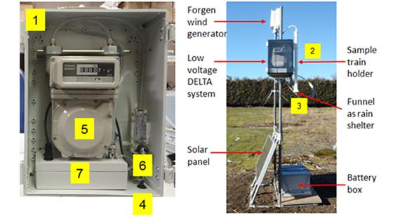
Detail of components in the monitoring enclosure of the low voltage DELTA® system. An example installation of the low voltage DELTA® system powered by wind and solar in the field is shown on the right. 1: Durable plastic enclosure 2: Sample train holder. 3: Sample inlet 4: Plug-in for sample train heater 5: Gas meter. 6: Rotameter. 7: Pump box